Mains Switch Over
Introduction
My dad has a large fish pond and would like to use the solar system to run the pumps, which require 150W of power. Can the solar system run the pumps 24/7?
Battery Capacity Overview
The battery system has a capacity of 170Ah at 24V, equating to 4kWh of total stored energy. In practice, the battery state of charge (SoC) should not drop below 20% to maintain battery health, resulting in 3.26kWh of usable energy.
This would run the pumps for approximately:
3.26kWh/150W = 21.76 hours
To edge on the side of caution I will also assume that the real capacity is less than this as the batteries are 4 years old now. A safety factor of 0.85 would result in 18.5 hours of continuous pump use.
My hope is that during the day the batteries will be charged up and the system will be able to run the pumps throughout the night.
If the state of charge falls below 20%, the system should cut off to protect the batteries, but the pumps must continue to operate. To achieve this, an interface is required to switch the power supply from solar to mains when necessary.
High Level Outline
For simplicity and ease of maintenance I would like to try and avoid any form of software. This should be achievable with the design below.
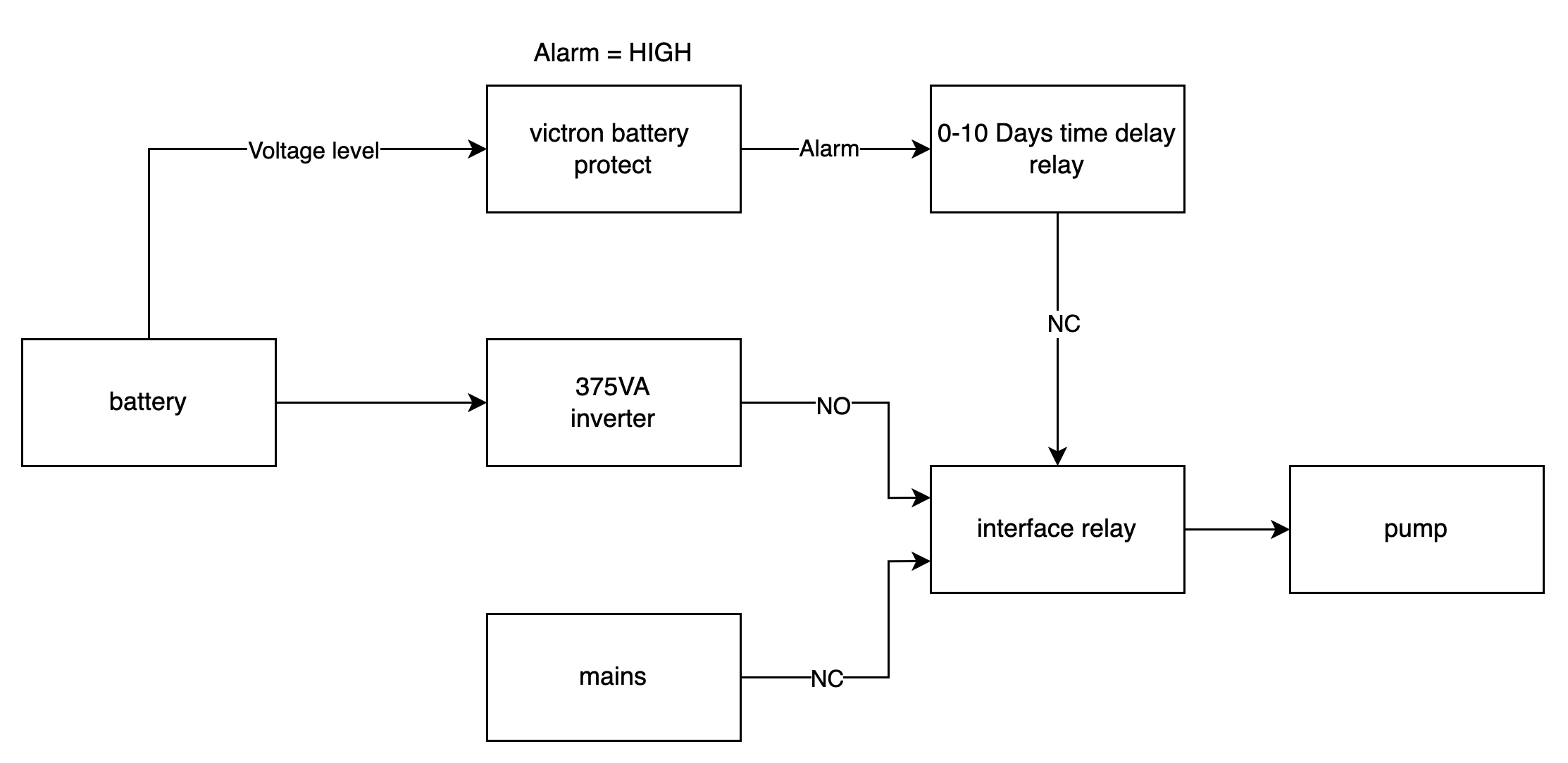
Fail Safe
If the solar system is off, the default state of the interface relay connects the pumps to the house mains and keeps the pumps running.
Normal Operation
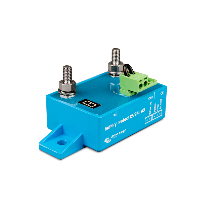
When the solar system is on, the Victron battery protect unit measures the battery voltage and enables the 24V system if the system voltage is above a programmable threshold value.
The alarm output of the battery protect unit in this scenario is low which results in the time delay relay staying in its normally connected state. This in turn enables the interface relay connecting the inverter to the pumps.
Should the system voltage go below the threshold value the time delay relay is triggered for 24 hours and the pumps are connected to mains power. Hopefully this is enough time for the batteries to be recharged by the solar system.
Components
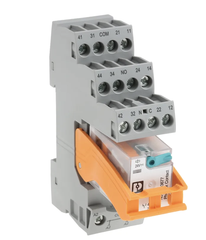
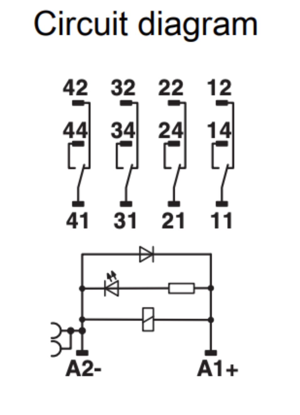
Interface Relay
The relay must be able to cope with the switching current of the pumps which draw 0.65A (150W/230VAC). The Phoenix Contact RIF-2-RSC-LDP-24DC/4X21 Series Interface Relay, DIN Rail Mount, 24V dc Coil, 4PDT, 4-Pole has a switching current of 1A at 230VAC and a maximum continuous draw of 6A.
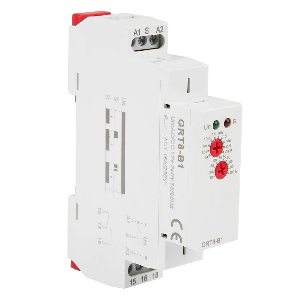
Time Delay Relay
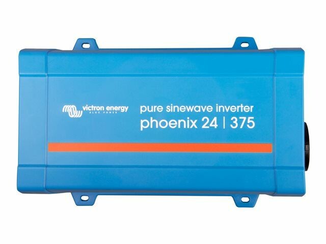
Victron Inverter
Battery Protect
BOM
| Part Number | Description | Manufacturer | Supplier | Cost (£) |
|---|---|---|---|---|
| 2903320 | Interface Relay | Phoenix Contact | RS | 13.26 |
| GRT8-B1 | Time Delay Relay | Geya | Amazon | 15.19 |
| Phoenix Pure Sine Wave Inverter - 24V 375VA | Inverter | Victron | 12V Planet | 107.14 |
| Smart Battery Protect 12/24V - 65A | Battery Protect | Victron | 12V Planet | 46.18 |
| 181.77 |
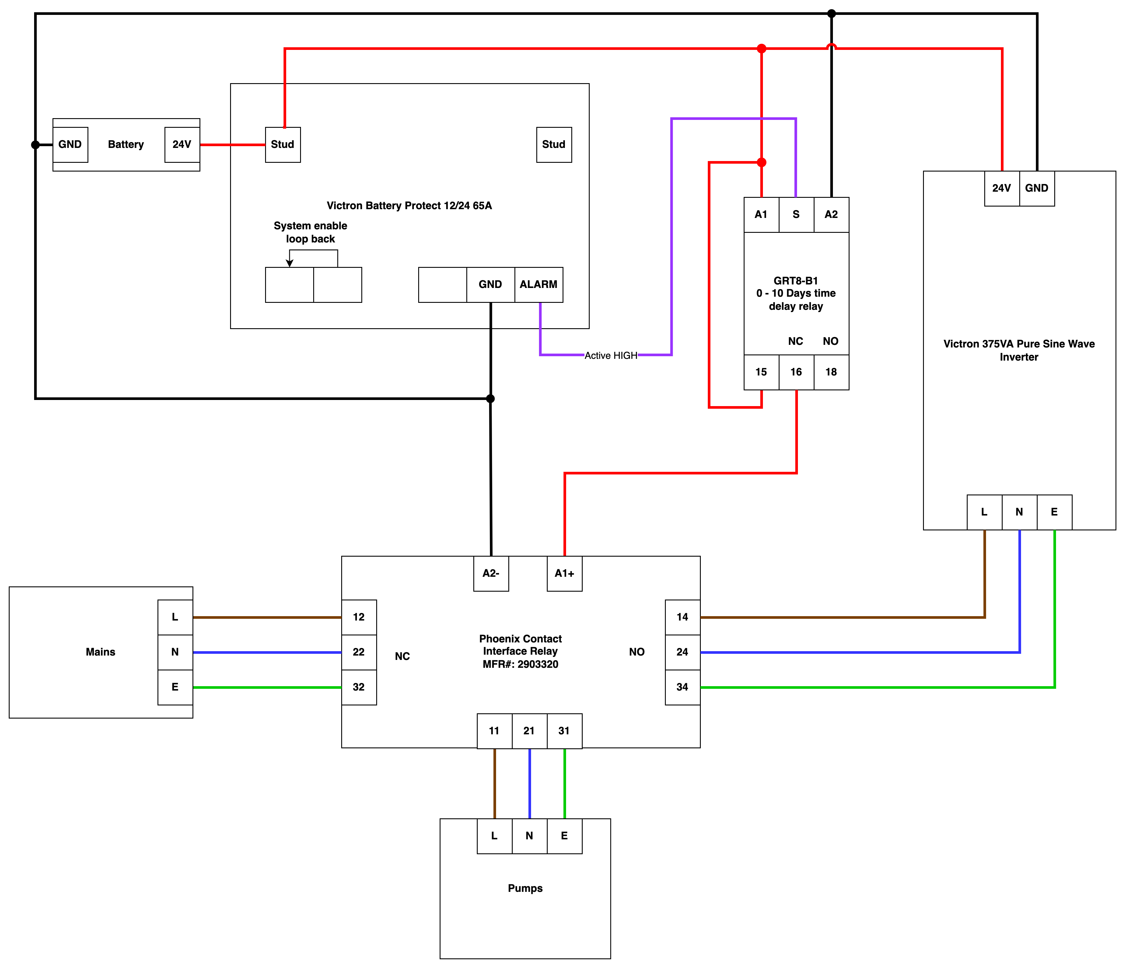
Wiring Diagram