DS18B20 Temperature Sensor PCB
Introduction
In 2013 I discovered the DS18B20 digital thermometer IC made by Maxim Integrated. It’s a great little IC that has provides a 12 bit temperature measurement and interfaces over the 1-Wire bus allowing multiple sensors to be daisy chained! Back then I used veraboard and some terrible soldering to create the strings of sensors used in my greenhouse. Well its now 2022 and I’m back to thinking about greenhouses.
PCB Design
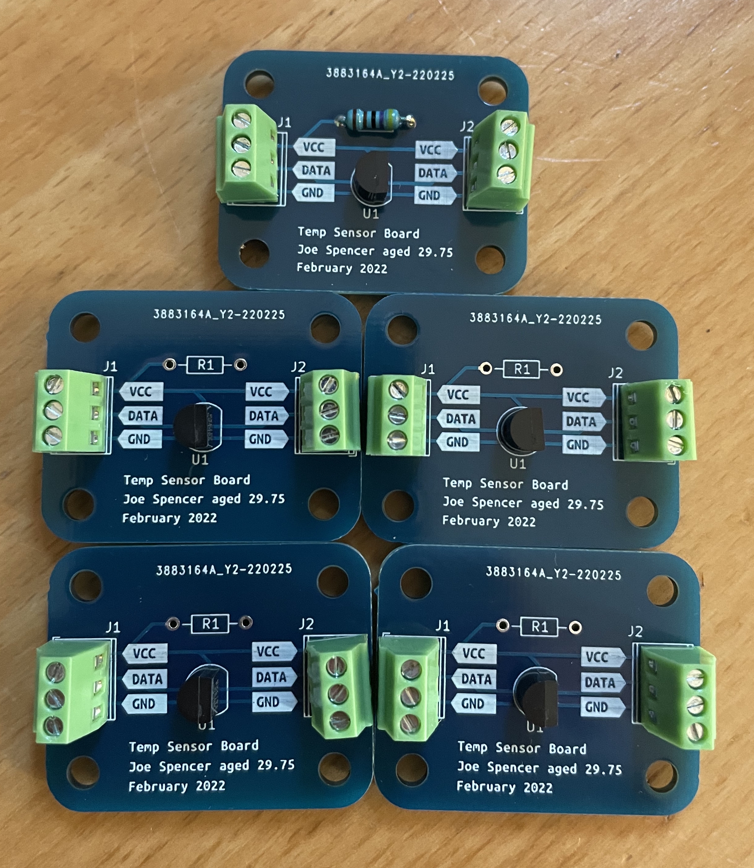
The design is about as simple as it comes. I’ve used 3x1 terminal blocks for the cable interface which could have been connectorised but I don’t really ever plan on unplugging them. Each board has a space for the pullup resistor which is required when using external power. The mounting hole size is 3mm.

Raspberry Pi
Enable 1-Wire interface
sudo rasbpi-config- select interface options
- select I7 1-Wire and enable
Wiring
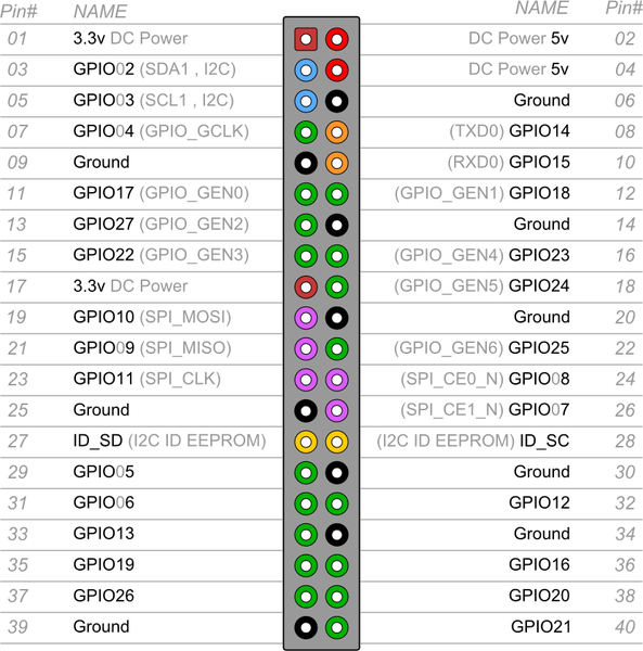
| PCB Pin | Pi Pin |
|---|---|
| Vcc | 01 |
| Data | 05 |
| Gnd | 06 |
pi pins 01 and 02 are closest to SD card.
Testing
navigate to cd /sys/bus/w1/devices
I have 5 board daisy chained listed below
28-301fbe0164ff  28-84ccbd0164ff  28-dfd5bd0164ff
28-4779be0164ff  28-c671b90164ff  w1_bus_master1
navigate to a sensors directory e.g. “28-301fbe0164ff”
cat w1_slave
returns
56 01 55 00 7f ff 0c 10 46 : crc=46 YES
56 01 55 00 7f ff 0c 10 46 t=21375
where t=21375 is the temperature in Celsius multiplied by 1000 so the temperature is 21.375 ± 0.5 degrees C.